وكالةدرجة أولى
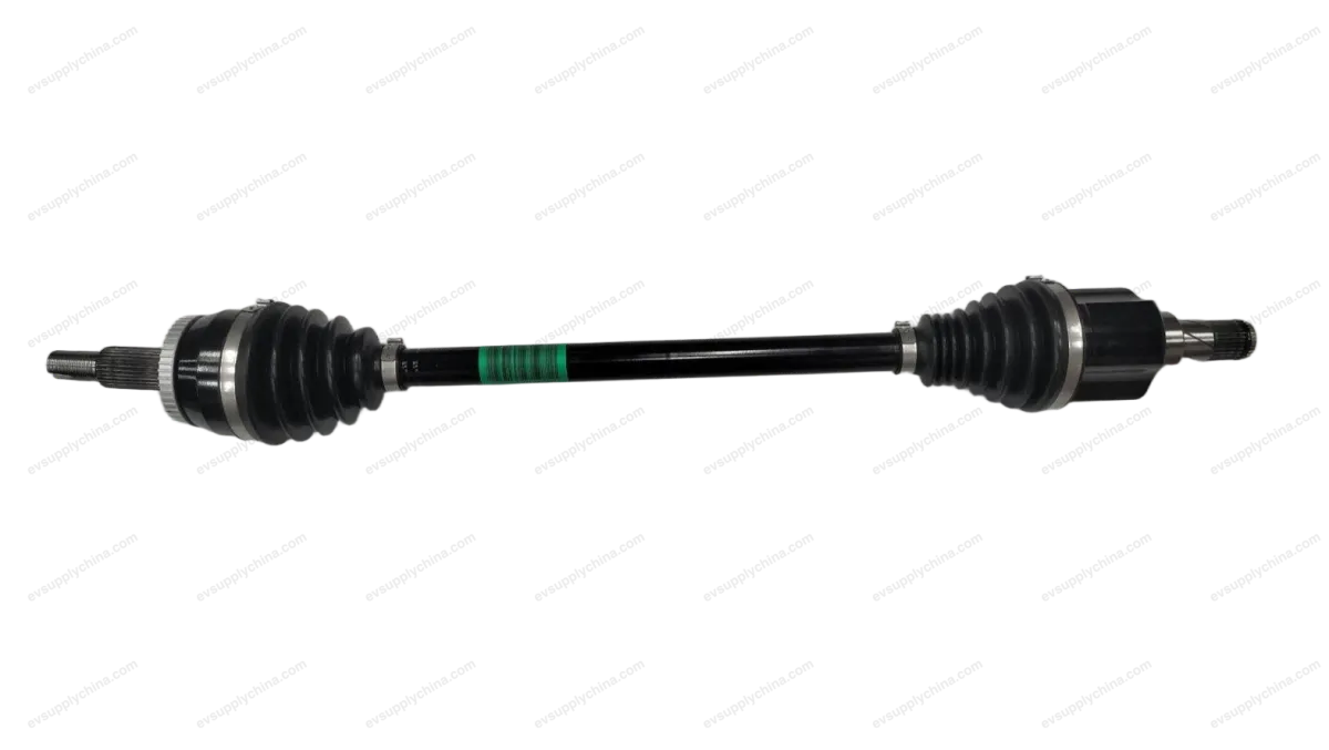
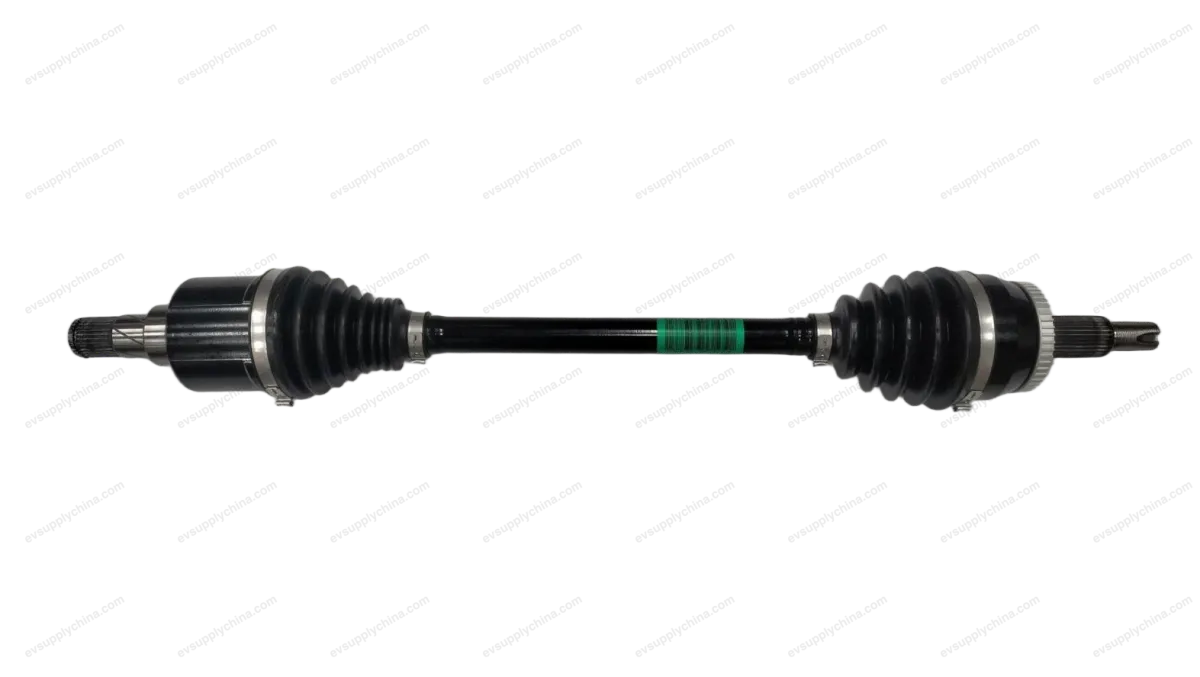
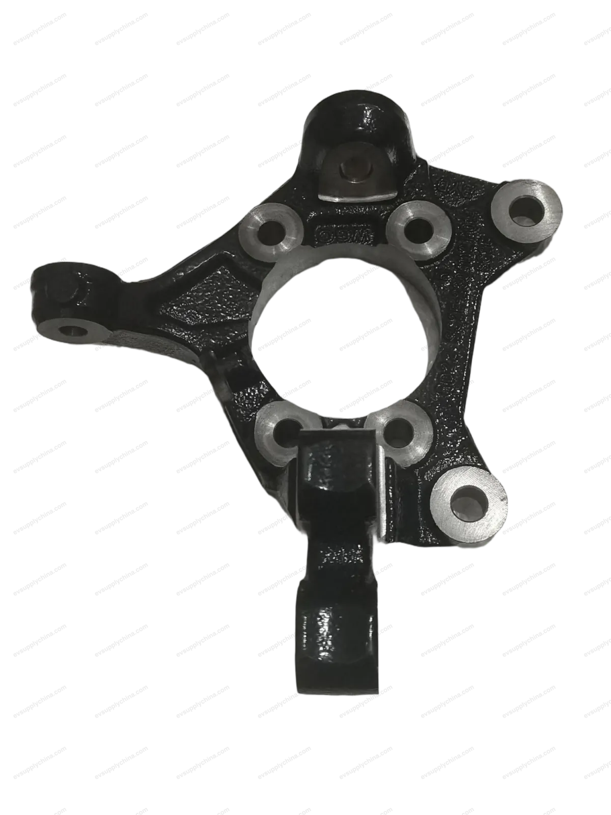
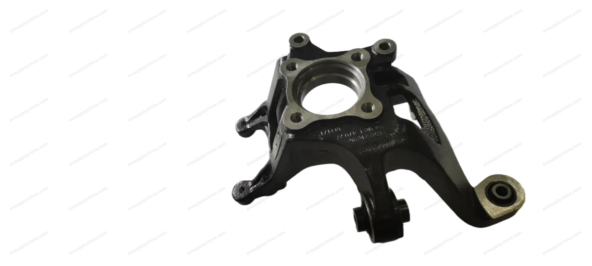
BYD Atto 3
شفّاط التوجيه الأمامي الأيسر
أكواد OE / المواد
13781671-00SC2E-2304111A$52USD
متوفرالمواصفات الفنية
- موديل السيارة
- BYD Atto 3
- تكوين التوجيه
- مقود يسار ومقود يمين
الشحن والإرجاع
شحن عالمي من الصين جواً أو بحراً. التسليم القياسي 5–30 يوم عمل، السريع 2–10 أيام عمل. تحسب تكلفة الشحن عند الدفع.
نافذة إرجاع 7 أيام للقطع غير المستخدمة في عبوتها الأصلية. تواصل معنا قبل إرجاع أي قطعة.
السيارات المتوافقة — شفّاط التوجيه الأمامي الأيسر
BYDYuan PLUS/Atto 3
2024شفّاط التوجيه الأمامي الأيسر دليل الورشة — BYD Atto 3
Left Front Steering Knuckle - Removal and Installation
Removal
- Remove the left front hub unit assembly. See Front Hub Unit Assembly - Removal and Installation
- Remove the left front ball stud press assembly. See Ball Stud Press Assembly - Removal and Installation
- Remove the left front wheel speed sensor. See Left Front Wheel Speed Sensor - Removal and Installation
- Detach the mechanical steering gear with tie rod assembly from the left front steering knuckle.
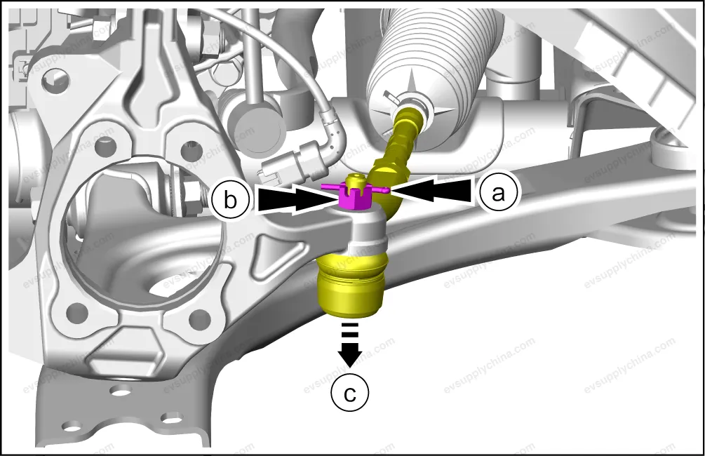
- Remove 1 fixing pin.
- Remove 1 fixing nuts.
- Remove the ball joint with the ball joint remover.
- Remove the left front steering knuckle.
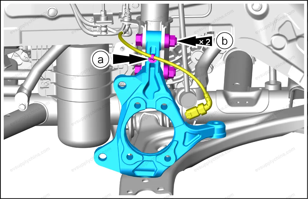
- Detach the wiring harness clip, and put aside the wiring harness
- Remove 2 fixing nuts, take out 2 fixing bolts, and take out the left front steering knuckle.
Installation
- The installation steps are opposite to the removal steps.
- Wheel alignment shall be carried out after the installation. See Four-Wheel Alignment
Right Front Steering Knuckle - Removal and Installation
Removal
- Remove the right front hub unit assembly. See Front Hub Unit Assembly - Removal and Installation
- Remove the right front ball stud press assembly. See Ball Stud Press Assembly - Removal and Installation
- Remove the right front wheel speed sensor. See Right Front Wheel Speed Sensor - Removal and Installation
- Detach the mechanical steering gear with tie rod assembly from the right front steering knuckle.
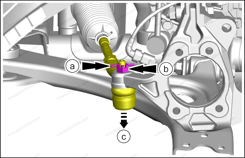
- Remove 1 fixing pin.
- Remove 1 fixing nut.
- Remove the ball joint with the ball joint remover.
- Remove the right front steering knuckle.
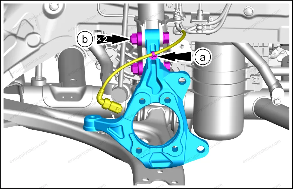
- Detach the wiring harness clip and put aside the wiring harness.
- Remove 2 fixing nuts/bolts, and take out the right front steering knuckle.
Installation
- The installation steps are opposite to the removal steps.
- Wheel alignment shall be carried out after the installation. See Four-Wheel Alignment