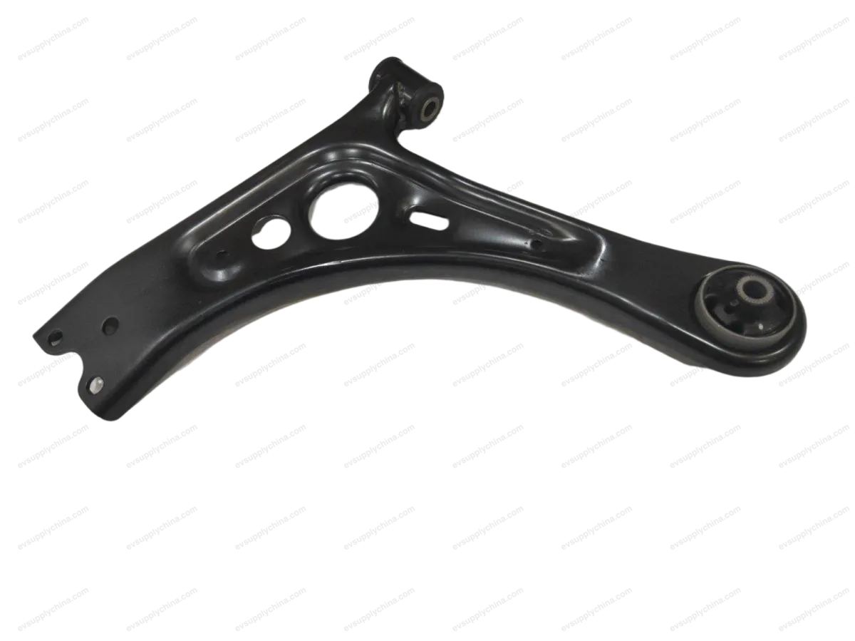
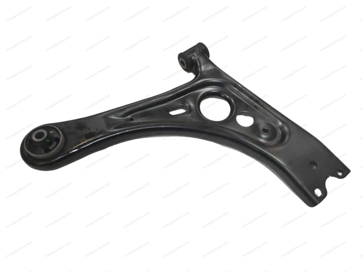
Rakitan lengan kendali suspensi belakang
Kode OE / Material
13437988-00SC2E-2914080ASpesifikasi Teknis
- Model Kendaraan
- BYD Atto 3
- Konfigurasi Kemudi
- Setir Kiri & Kanan
- Kategori
- Wishbone & Lengan Kontrol
Pengiriman & Pengembalian
Dikirim ke seluruh dunia dari Tiongkok melalui pengiriman udara atau laut. Pengiriman standar 5–30 hari kerja, ekspres 2–10 hari kerja. Biaya pengiriman dihitung saat checkout.
Jendela pengembalian 7 hari untuk barang yang belum digunakan dalam kemasan asli. Hubungi kami sebelum mengembalikan barang apa pun.
Kendaraan yang Kompatibel — Rakitan lengan kendali suspensi belakang
Rakitan lengan kendali suspensi belakang Panduan Bengkel — BYD Atto 3
Rear Suspension Control Arm Assembly - Removal and Installation
Removal
- Remove the left rear wheel assembly. See Wheel Assembly - Removal and Installation
- Remove the rear suspension left towing arm assembly. See Rear Suspension Left Towing Arm Assembly - Removal and Installation
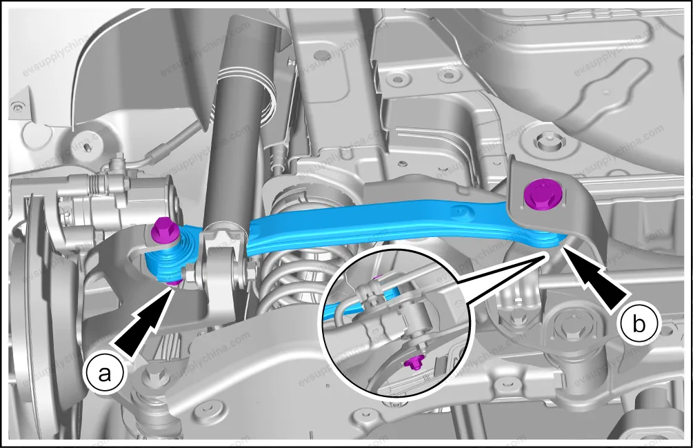
- Remove the rear suspension control arm assembly.
- Remove 1 fixing nuts.
- Remove 1 fixing nut/bolt, and take out the rear suspension control arm assembly.
Caution The removal and installation methods of the left and right rear suspension control arm assemblies are the same. The left rear suspension control arm assembly is taken as an example.
Installation
- The installation steps are opposite to the removal steps.
Rear Suspension Lower Arm Assembly - Removal and Installation
Removal
- Remove the left rear wheel assembly. See Wheel Assembly - Removal and Installation
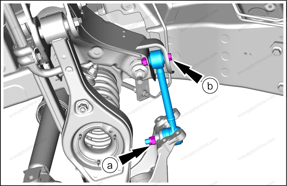
- Remove the left/right rear stabilizer bar tie rod and ball joint assemblies. See Rear Stabilizer Bar Tie Rod and Ball Joint Assembly - Removal and Installation
- Remove the rear suspension lower arm assembly.
- Remove 1 fixing nut/bolt.
- Remove 1 fixing nut/bolt.
- Take out the rear suspension lower arm assembly and rear coil spring.
- To replace the rear suspension lower arm assembly, remove the following accessories from it:
Caution Before removing the fixing nut/bolt of the rear suspension lower arm assembly, use the equipment to support the rear suspension lower arm assembly. Take care when removing the rear suspension lower arm assembly to prevent personal injury caused by the rebound of the rear suspension lower arm assembly and the rear coil spring. Before removing the rear suspension lower arm assembly, loosen the nuts on the eccentric bolts of the rear suspension lower arm assembly and the rear sub-frame assembly. Remove the connecting nuts/bolts between the rear suspension lower arm assembly and the rear steering knuckle. Slowly lower the support equipment. Remove the eccentric bolts/female from the rear suspension lower arm assembly and the rear sub-frame assembly. Take out the rear suspension lower arm assembly, the rear coil spring, the rear coil spring upper cushion, and the rear coil spring lower cushion.
Installation
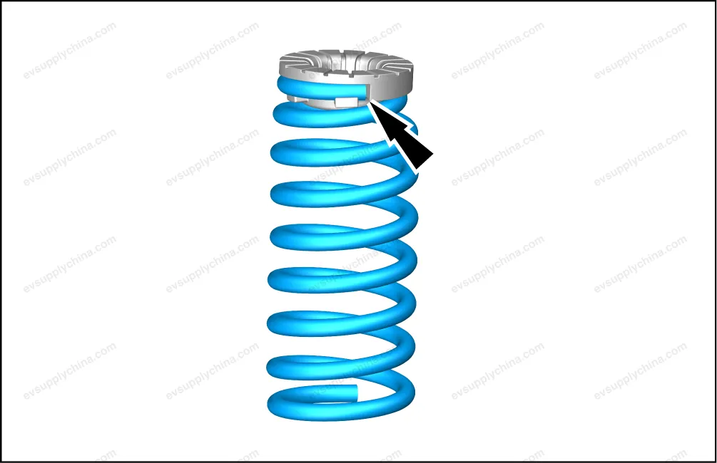
- During installation, align the upper part of the rear coil spring with the assembly point of the upper cushion.
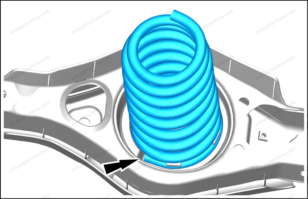
- During installation, align the lower part of the rear coil spring with the assembly point of the lower cushion.
- The other installation steps are opposite to the removal steps.
- After the installation, implement four-wheel alignment. See Four-Wheel Alignment
Caution When installing the rear suspension lower arm assembly and the rear coil spring on the vehicle, install the eccentric bolts on the rear suspension lower arm assembly and the rear sub-frame assembly first. Screw on the nuts by hand. Use the equipment to support and raise the rear suspension lower arm assembly and the rear coil spring to the assembly position. Install the bolts of the rear suspension lower arm assembly and the rear steering knuckle. And then screw on the nuts by hand. When installing the rear suspension lower arm assembly, use the support equipment to raise it to the original position, and then tighten the nuts/bolts.
Rear Suspension Upper Left Arm Assembly - Removal and Installation
Removal
- Remove the left rear wheel assembly. See Wheel Assembly - Removal and Installation
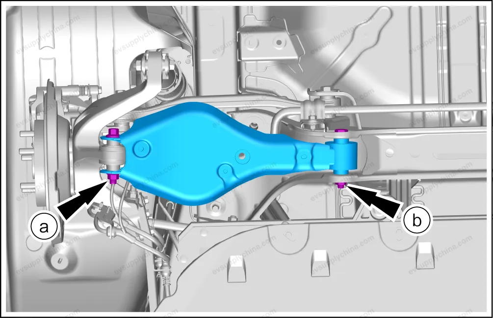
- Remove the rear suspension upper left arm assembly.
- Remove 1 fixing nut/bolt.
- Remove 1 fixing nut/bolt.
- Take out the rear suspension upper left arm assembly.
Caution The removal and installation methods of the rear suspension upper left arm assembly and the rear suspension upper right arm assembly are the same. The left side is taken as an example.
Installation
- The installation steps are opposite to the removal steps.
- After the installation, implement four-wheel alignment. See Four-Wheel Alignment
Caution When installing the rear suspension upper left arm assembly, use the support equipment to raise it to the original position and then tighten the nuts/bolts.
Rakitan lengan kendali suspensi belakang Diagram Pemasangan — BYD Atto 3

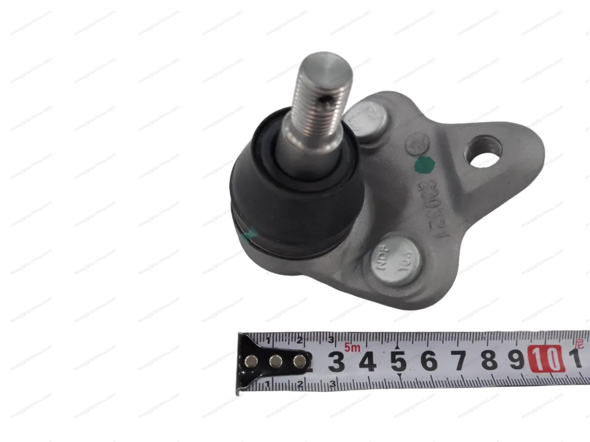
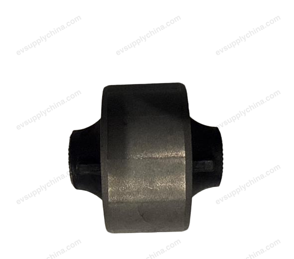
Komponen lain dalam rakitan ini