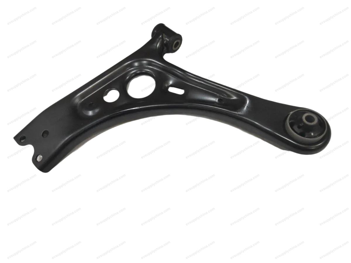
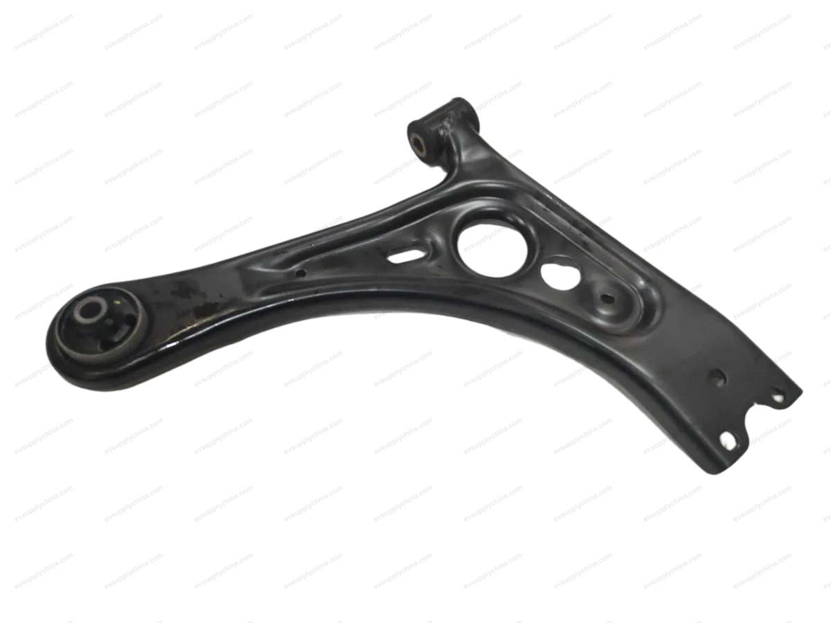
مجموعة ذراع الجر الأيسر للتعليق الخلفي
أكواد OE / المواد
13437987-00SC2E-2914100Aالمواصفات الفنية
- موديل السيارة
- BYD Atto 3
- تكوين التوجيه
- مقود يسار ومقود يمين
- الفئة
- أذرع التحكم
الشحن والإرجاع
شحن عالمي من الصين جواً أو بحراً. التسليم القياسي 5–30 يوم عمل، السريع 2–10 أيام عمل. تحسب تكلفة الشحن عند الدفع.
نافذة إرجاع 7 أيام للقطع غير المستخدمة في عبوتها الأصلية. تواصل معنا قبل إرجاع أي قطعة.
السيارات المتوافقة — مجموعة ذراع الجر الأيسر للتعليق الخلفي
مجموعة ذراع الجر الأيسر للتعليق الخلفي دليل الورشة — BYD Atto 3
Rear Suspension Upper Left Arm Assembly - Removal and Installation
Removal
- Remove the left rear wheel assembly. See Wheel Assembly - Removal and Installation
- Remove the rear suspension upper left arm assembly.
- Remove 1 fixing nut/bolt.
- Remove 1 fixing nut/bolt.
- Take out the rear suspension upper left arm assembly.
Caution The removal and installation methods of the rear suspension upper left arm assembly and the rear suspension upper right arm assembly are the same. The left side is taken as an example.
Installation
- The installation steps are opposite to the removal steps.
- After the installation, implement four-wheel alignment. See Four-Wheel Alignment
Caution When installing the rear suspension upper left arm assembly, use the support equipment to raise it to the original position and then tighten the nuts/bolts.
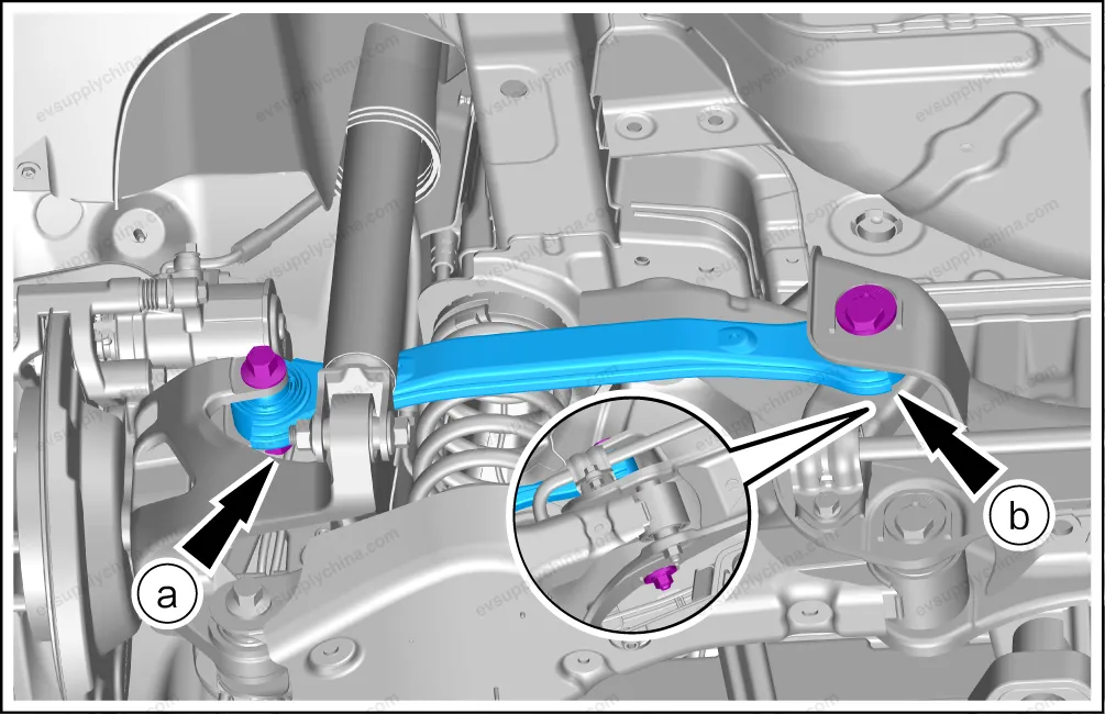
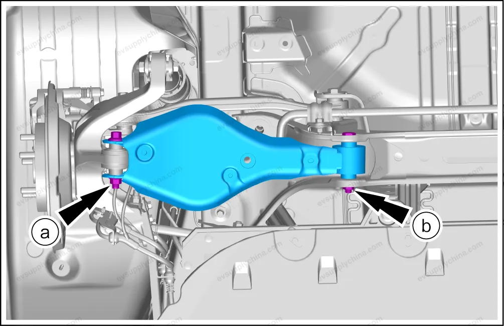
Rear Suspension Left Towing Arm Assembly - Removal and Installation
Removal
- Remove the left rear wheel assembly. See Wheel Assembly - Removal and Installation
- Remove the power battery assembly. See Power Battery Assembly - Removal and Installation
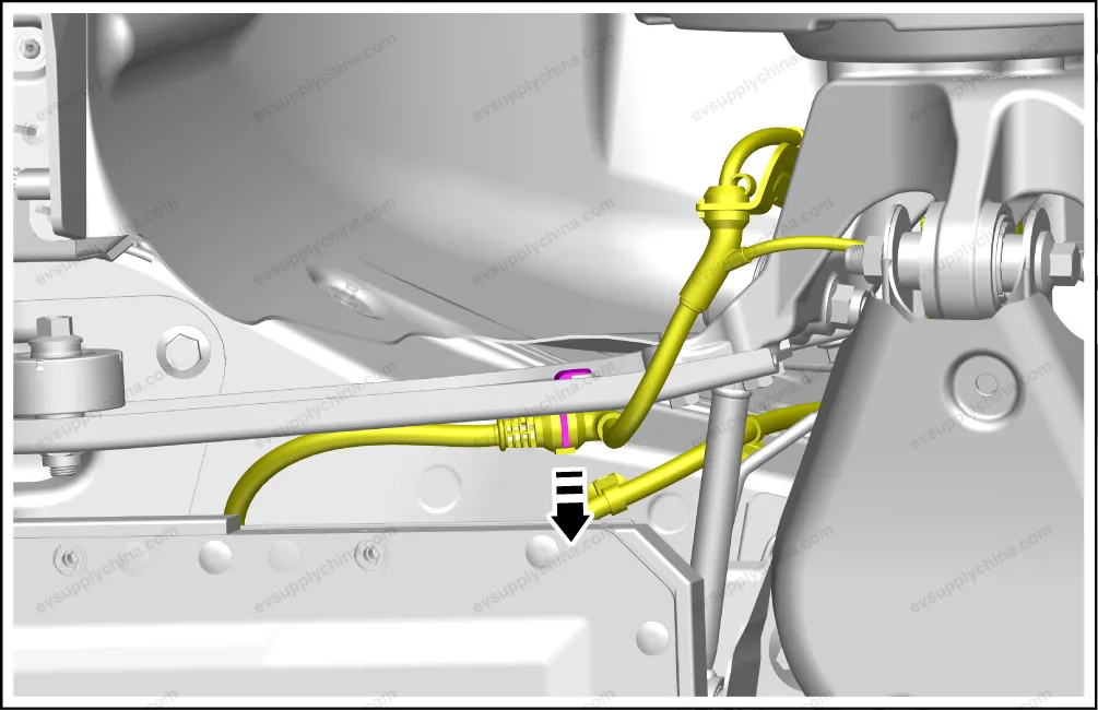
- Detach the floor wiring harness from the rear suspension left towing arm assembly.
- Remove the rear suspension left towing arm assembly.
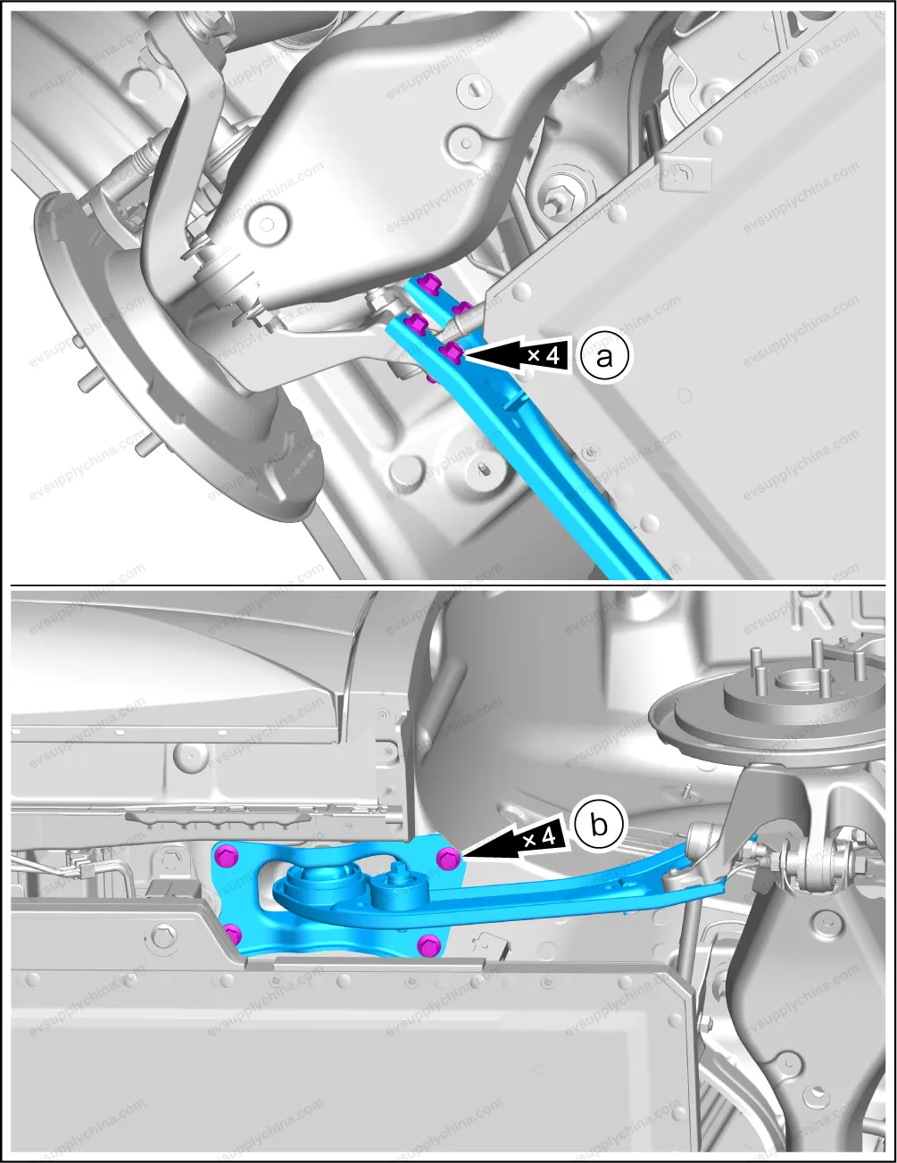
- Remove 4 fixing bolt.
- Remove 4 fixing bolts, and take out the rear suspension left towing arm assembly with the left rear towing arm mounting bracket.
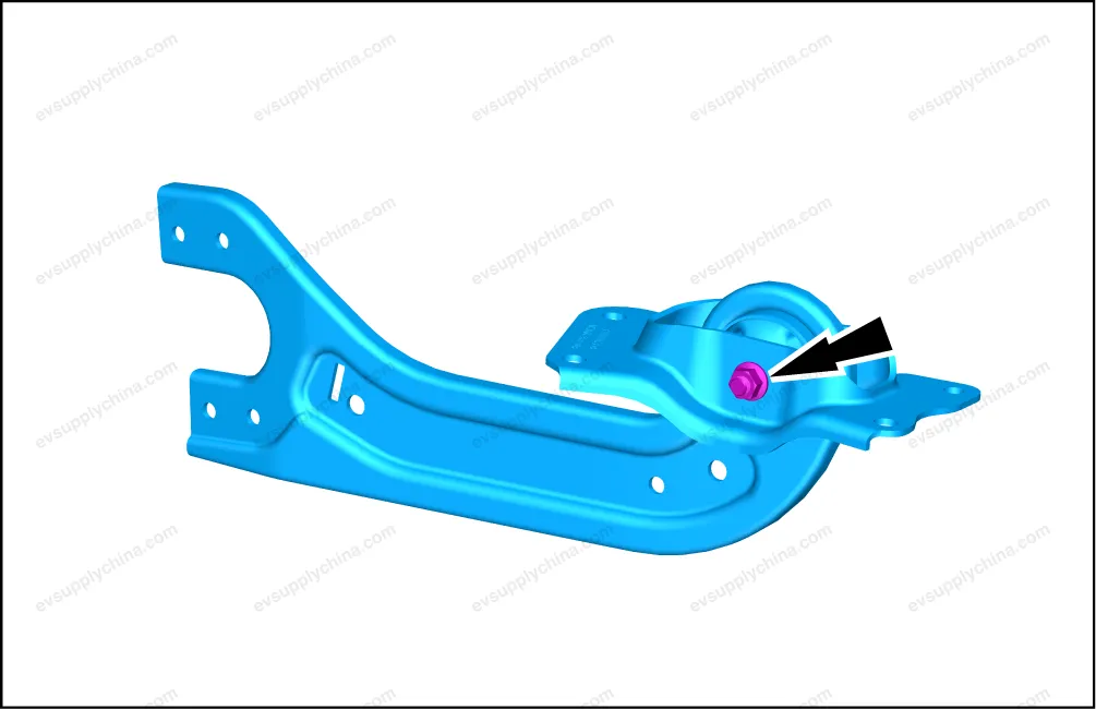
- Remove 1 nut/bolt, and separate the rear suspension left towing arm assembly from the left rear towing arm mounting bracket.
Caution Before removing the mounting bracket of the right rear towing arm, use a marker pen to mark the assembly position in case it is not on the same plane during installation.
Installation
- The installation steps are opposite to the removal steps.
Rear Suspension Lower Arm Assembly - Removal and Installation
Removal
- Remove the left rear wheel assembly. See Wheel Assembly - Removal and Installation
- Remove the left/right rear stabilizer bar tie rod and ball joint assemblies. See Rear Stabilizer Bar Tie Rod and Ball Joint Assembly - Removal and Installation
- Remove the rear suspension lower arm assembly.
- Remove 1 fixing nut/bolt.
- Remove 1 fixing nut/bolt.
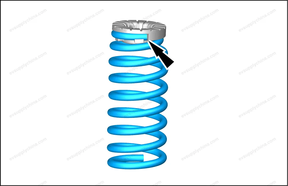
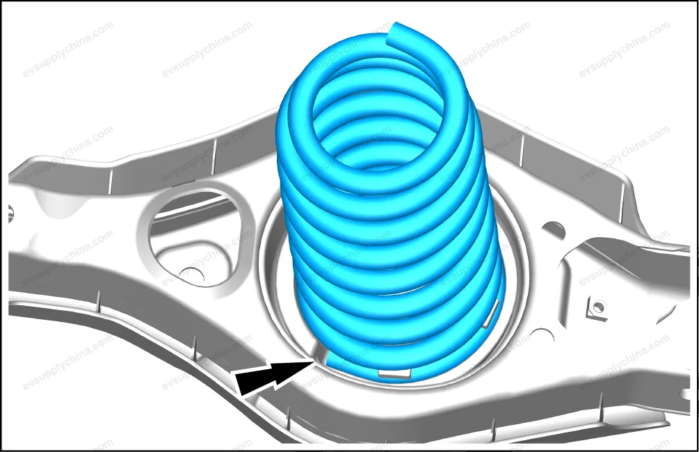
- Take out the rear suspension lower arm assembly and rear coil spring.
- To replace the rear suspension lower arm assembly, remove the following accessories from it:
Caution Before removing the fixing nut/bolt of the rear suspension lower arm assembly, use the equipment to support the rear suspension lower arm assembly. Take care when removing the rear suspension lower arm assembly to prevent personal injury caused by the rebound of the rear suspension lower arm assembly and the rear coil spring. Before removing the rear suspension lower arm assembly, loosen the nuts on the eccentric bolts of the rear suspension lower arm assembly and the rear sub-frame assembly. Remove the connecting nuts/bolts between the rear suspension lower arm assembly and the rear steering knuckle. Slowly lower the support equipment. Remove the eccentric bolts/female from the rear suspension lower arm assembly and the rear sub-frame assembly. Take out the rear suspension lower arm assembly, the rear coil spring, the rear coil spring upper cushion, and the rear coil spring lower cushion.
Installation
- During installation, align the upper part of the rear coil spring with the assembly point of the upper cushion.
- During installation, align the lower part of the rear coil spring with the assembly point of the lower cushion.
- The other installation steps are opposite to the removal steps.
- After the installation, implement four-wheel alignment. See Four-Wheel Alignment
Caution When installing the rear suspension lower arm assembly and the rear coil spring on the vehicle, install the eccentric bolts on the rear suspension lower arm assembly and the rear sub-frame assembly first. Screw on the nuts by hand. Use the equipment to support and raise the rear suspension lower arm assembly and the rear coil spring to the assembly position. Install the bolts of the rear suspension lower arm assembly and the rear steering knuckle. And then screw on the nuts by hand. When installing the rear suspension lower arm assembly, use the support equipment to raise it to the original position, and then tighten the nuts/bolts.
مجموعة ذراع الجر الأيسر للتعليق الخلفي مخطط التركيب — BYD Atto 3

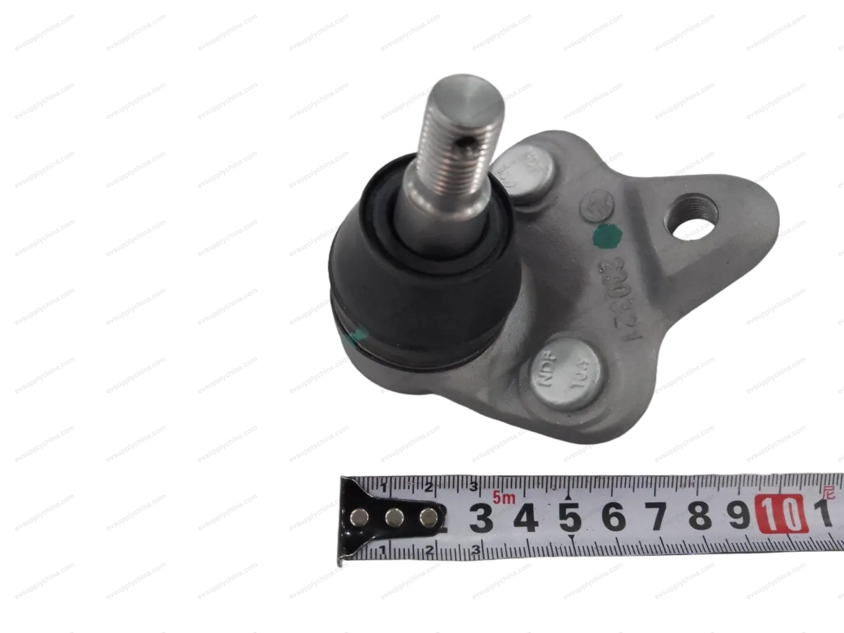
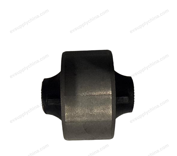
قطع أخرى في هذه المجموعة